Carbon Steel Pipe
Stainless Steel Pipe
Fittings
OCTG
Steel Structure
Value-Added Products
Clad Pipe
Coated Steel Pipe
Technical Data
Photos
-
Raised Face Flanges (RF)

-
Flat Face Flanges (FF)

-
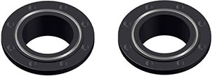
Ring Type Joint Flanges (RTJ)
-
ASME B16.1 - Gray Iron Pipe Flanges and Flanged Fittings: Classes 25, 125, and 250
-
ASME B16.5 - Pipe Flanges and Flanged Fittings: NPS 1/2 through NPS 24 Metric/Inch Standard
-
ASME B16.20 - Ring Joint Gaskets and Grooves for Steel Pipe Flanges
-
ASME B16.21 - Nonmetallic Flat Gaskets for Pipe Flanges
-
ASME B16.24 - Cast Copper Alloy Pipe Flanges and Flanged Fittings: Classes 150, 300, 600, 900, 1500, and 2500
-
ASME B16.34 - Large Diameter Steel Flanges (NPS 26 through NPS 60)
-
ASME B16.36 - Orifice Flanges
-
ASME B16.42 - Ductile Iron Pipe Flanges and Flanged Fittings: Classes 150 and 300
-
ASME B16.47 - Large Diameter Steel Flanges (NPS 26 Through NPS 60)
-
ASTM A105 - Specification for Carbon Steel Forgings for Piping Applications
-
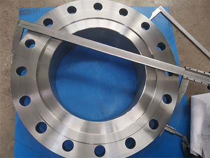
ASTM A182 - Specification for Forged or Rolled Alloy Steel Pipe Flanges, Forged Fittings, and Valves and Parts for High Temperature Service
-
ASTM A193 - Specification for Alloy Steel and Stainless Steel Bolting Materials for High Temperature Service
-
ASTM A194 - Specification for Carbon and Alloy Steel Nuts for Bolts for High Pressure and High Temperature Service
-
ASTM A694 - Specification for Carbon and Alloy Steel Forgings for Pipe Flanges, Fittings, Valves, and Parts for High-Pressure Transmission Service
-
ASTM A707 - Specification for Flanges, Forged, Carbon and Allow Steel for Low Temperature Service
-
AWWA C115 - Standard for Flanged Ductile Iron Pipe with Ductile-Iron or Gray-Iron Threaded Flanges
-
Flange - ASME B16.36, Orifice Flange (1/2"-24")
-
Slip-on Flange: Class 300, Class 400, Class 600, Class 900, Class 1500
-
Threaded Flange: Class 300, Class 400, Class 600, Class 900, Class 1500
-
Weld Neck Flange: Class 300, Class 400, Class 600, Class 900, Class 1500, Class 2500
-
-
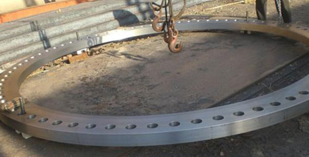
Flange - Industry Standard Flange (also called Large Diameter Flange) (26"-larger)
-
Industry Standard Flanges have no national standard code or are they covered by any governing body.
-
Blind Flange: Class 75, Class 125, Class 175, Class 250, Class 350
-
Weld Neck Flange: Class 75, Class 125LW, Class 125, Class 175, Class 250, Class 350
-
Slip-on Flange: Class 75, Class 125LW, Class 125, Class 175, Class 250, Class 350
-
-
-
Flange - AWWA Standard Flange
-
AWWA C207
-
Steel Ring Flange: Class B, Class D, Class E, Class F
-
Steel Hub Flange: Class D, Class E
-
Blind Flange: Class B, Class D, Class E, Class F
-
-
AWWA C207
-
Steel Ring Flange: Class B, Class D, Class E, Class F
-
Steel Hub Flange: Class D, Class E
-
Blind Flange: Class B, Class D, Class E, Class F
-
-
Flange sizes
1/2”-60” (DN15-DN3000)
Thickness Schedule 10(S) to SCH 16
Flange facing
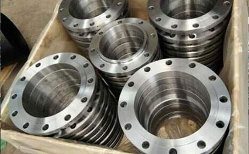
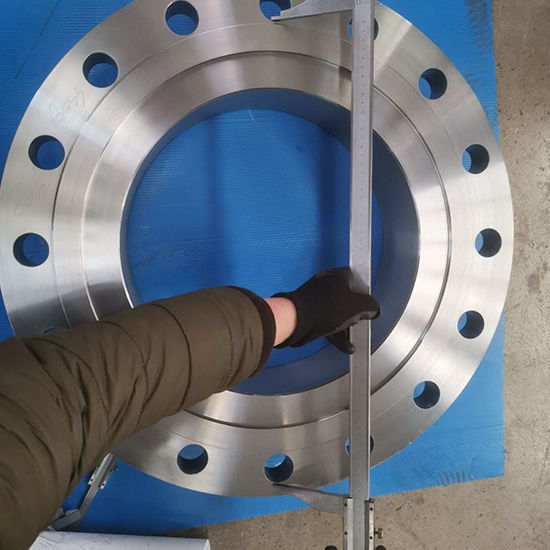
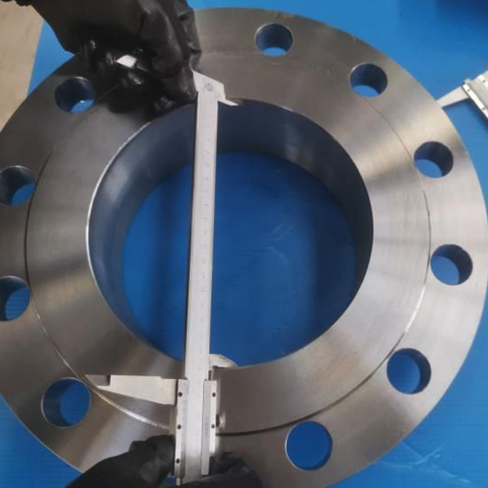
There are three primary types of flange facings. Not all facings are available with each end connection. This is based on the design of the flange and design of the piping system.
Flange pressure classes
Flanges are normally manufactured in seven basic ratings: 150 Lb, 300 Lb, 400 Lb, 600 Lb, 900 Lb, 1500 Lb and 2500 Lb. The ratings can be expressed in different ways but mean the same thing - 150 Lb, 150 Lbs, 150# or Class 150.

Flange types
Blind flange
A blind flange, abbreviated as BF, is a piping component for covering or closing the end of a pipe, valve, vessel or tank.
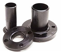
Lap joint flange
A lap joint flange, abbreviated as LJF, is a flange that consists of two parts, a stub end and the backing flange.
In general, the thickness of the hub is between ¼” to 3/8”.
Raised face flange
the most common type of flange facing is the raised face flange, abbreviated as RF. It is used in almost all applications in high and low pressures and temperatures.
The face of the flange is either 1/16” or 1/4” depending on the pressure class. ANSI 300 and under have a 1/16” raised face and ANSI 400 and above have a 1/4” raised face.
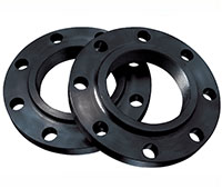
Slip-on flange
Slip-on flanges, abbreviated as SOF, are designed to slip over the outside of pipe, long-tangent elbows, reducers, and swages.
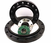
Thread flange
The threaded flange, abbreviated as TRHF, is similar to a slip-on flange, but has internal threads. It is normally used for low pressure and not used where temperature or stress is very high. This flange has a raised face.
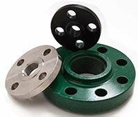
Socket weld flange
The socket weld flange, abbreviated as SWF, is similar to a slip-on flange, except only one fillet weld is made to the flange and pipe. Pipe is welded to socket weld flanges by inserting the pipe into the socket and backing the piping out between 1/16” and 1/8”.
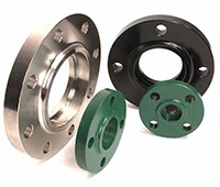
Weld neck flange
the weld neck flange, abbreviated as WNF, is a flange type that is usually used with pipes, as opposed to pressure vessels.
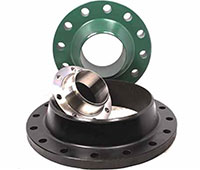
Flange standard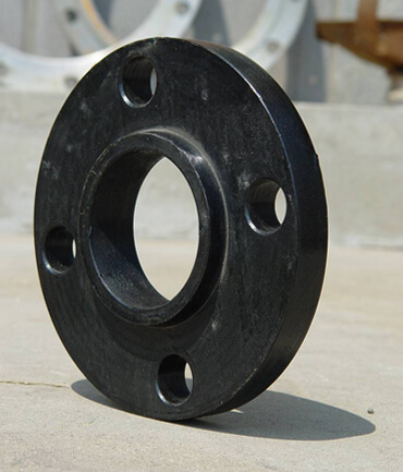
ASME standard
ASTM standard
AWWA standard
General pipe flange standards
Sizes1/2”-60” NPS (DN15-DN3000), SCH10,STD,SCH40,SCH60,XS,SCH80,SCH120,SCH160,XXS
FacingRF/ FM/ M/ T G/ RF / FF / RTJ Class Class150-Class2500
TypesSocket Weld, Slip On, Blind,Screwed, Ring Joint, Weld Neck, Long Weld Neck
| CLASS 150 According to ASTM A/SA-105; ANSI B16.5 | |||||||||||
|
Nominal Pipe Size |
Outside Diam. of Flange (O) |
Thick. of Flange (C) |
Diam. of Raised Face (R) |
Diam. of Hub at Base (X) |
Length thru Hub (Y) |
Min. Thread Length (T) |
No. of Holes |
Diam. of Holes |
Diam. of Bolts |
Diam. of Bolt Circle |
Approx. Weight (in Pounds) |
| ½ | 3.5 | 0.44 | 1.38 | 1.19 | 0.62 | 0.62 | 4 | 0.62 | 0.5 | 2.38 | 1 |
| ¾ | 3.88 | 0.5 | 1.69 | 1.5 | 0.62 | 0.62 | 4 | 0.62 | 0.5 | 2.75 | 2 |
| 1 | 4.25 | 0.56 | 2 | 1.94 | 0.69 | 0.69 | 4 | 0.62 | 0.5 | 3.12 | 2 |
| 1 ¼ | 4.62 | 0.62 | 2.5 | 2.31 | 0.81 | 0.81 | 4 | 0.62 | 0.5 | 3.5 | 3 |
| 1 ½ | 5 | 0.69 | 2.88 | 2.56 | 0.88 | 0.88 | 4 | 0.62 | 0.5 | 3.88 | 3 |
| 2 | 6 | 0.75 | 3.62 | 3.06 | 1 | 1 | 4 | 0.75 | 0.62 | 4.75 | 5 |
| 2 ½ | 7 | 0.88 | 4.12 | 3.56 | 1.12 | 1.12 | 4 | 0.75 | 0.62 | 5.5 | 7 |
| 3 | 7.5 | 0.94 | 5 | 4.25 | 1.19 | 1.19 | 4 | 0.75 | 0.62 | 6 | 8 |
| 3 ½ | 8.5 | 0.94 | 5.5 | 4.81 | 1.25 | 1.25 | 8 | 0.75 | 0.62 | 7 | 11 |
| 4 | 9 | 0.94 | 6.19 | 5.31 | 1.31 | 1.31 | 8 | 0.75 | 0.62 | 7.5 | 13 |
| 5 | 10 | 0.94 | 7.31 | 6.44 | 1.44 | 1.44 | 8 | 0.88 | 0.75 | 8.5 | 15 |
| 6 | 11 | 1 | 8.5 | 7.56 | 1.56 | 1.56 | 8 | 0.88 | 0.75 | 9.5 | 19 |
| 8 | 13.5 | 1.12 | 10.62 | 9.69 | 1.75 | 1.75 | 8 | 0.88 | 0.75 | 11.75 | 30 |
| 10 | 16 | 1.19 | 12.75 | 12 | 1.94 | 1.94 | 12 | 1 | 0.88 | 14.25 | 43 |
| 12 | 19 | 1.25 | 15 | 14.38 | 2.19 | 2.19 | 12 | 1 | 0.88 | 17 | 64 |
| 14 | 21 | 1.38 | 16.25 | 15.75 | 2.25 | 2.25 | 12 | 1.12 | 1 | 18.75 | 90 |
| 16 | 23.5 | 1.44 | 18.5 | 18 | 2.5 | 2.5 | 16 | 1.12 | 1 | 21.25 | 98 |
| 18 | 25 | 1.56 | 21 | 19.88 | 2.69 | 2.69 | 16 | 1.25 | 1.13 | 22.75 | 130 |
| 20 | 27.5 | 1.69 | 23 | 22 | 2.88 | 2.88 | 20 | 1.25 | 1.12 | 25 | 165 |
| 24 | 32 | 1.88 | 27.25 | 26.12 | 3.25 | 3.25 | 20 | 1.38 | 1.25 | 29.5 | 220 |
|
CLASS 300 According to ASTM A/SA-105; ANSI B16.5 |
||||||||||||
|
Nominal Pipe Size |
Outside Diam. of Flange (O) |
Thick. of Flange (C) |
Diam. of Raised Face (R) |
Diam. of Hub at Base (X) |
Length thru Hub (Y) |
Min. Thread Length (T) |
Min. Counter Bore (Q) |
No. of Holes |
Diam. of Holes |
Diam. of Bolts |
Diam. of Bolt Circle |
Approx. Weight (in Pounds) |
| 1/2 | 3.75 | 0.56 | 1.38 | 1.5 | 0.88 | 0.62 | 0.93 | 4 | 0.62 | 0.5 | 2.62 | 2 |
| 3/4 | 4.62 | 0.62 | 1.69 | 1.88 | 1 | 0.62 | 1.14 | 4 | 0.75 | 0.62 | 3.25 | 3 |
| 1 | 4.88 | 0.69 | 2 | 2.12 | 1.06 | 0.69 | 1.41 | 4 | 0.75 | 0.62 | 3.5 | 3 |
| 1 1/4 | 5.25 | 0.75 | 2.5 | 2.5 | 1.06 | 0.81 | 1.75 | 4 | 0.75 | 0.62 | 3.88 | 4 |
| 1 1/2 | 6.12 | 0.81 | 2.88 | 2.75 | 1.19 | 0.88 | 1.99 | 4 | 0.88 | 0.75 | 4.5 | 6 |
| 2 | 6.5 | 0.88 | 3.62 | 3.31 | 1.31 | 1.12 | 2.5 | 8 | 0.75 | 0.62 | 5 | 7 |
| 2 1/2 | 7.5 | 1 | 4.12 | 3.94 | 1.5 | 1.25 | 3 | 8 | 0.88 | 0.75 | 5.88 | 10 |
| 3 | 8.25 | 1.12 | 5 | 4.62 | 1.69 | 1.25 | 3.63 | 8 | 0.88 | 0.75 | 6.62 | 13 |
| 3 1/2 | 9 | 1.19 | 5.5 | 5.25 | 1.75 | 1.44 | 4.13 | 8 | 0.88 | 0.75 | 7.25 | 17 |
| 4 | 10 | 1.25 | 6.19 | 5.75 | 1.88 | 1.44 | 4.63 | 8 | 0.88 | 0.75 | 7.88 | 22 |
| 5 | 11 | 1.38 | 7.31 | 7 | 2 | 1.69 | 5.69 | 8 | 0.88 | 0.75 | 9.25 | 28 |
| 6 | 12.5 | 1.44 | 8.5 | 8.12 | 2.06 | 1.81 | 6.75 | 12 | 0.88 | 0.75 | 10.62 | 39 |
| 8 | 15 | 1.62 | 10.62 | 10.25 | 2.44 | 2 | 8.75 | 12 | 1 | 0.88 | 13 | 58 |
| 10 | 17.5 | 1.88 | 12.75 | 12.62 | 2.62 | 2.19 | 10.88 | 16 | 1.12 | 1 | 15.25 | 81 |
| 12 | 20.5 | 2 | 15 | 14.75 | 2.88 | 2.38 | 12.94 | 16 | 1.25 | 1.12 | 17.75 | 115 |
| 14 | 23 | 2.12 | 16.25 | 16.75 | 3 | 2.5 | 14.19 | 20 | 1.25 | 1.12 | 20.25 | 165 |
| 16 | 25.5 | 2.25 | 18.5 | 19 | 3.25 | 2.69 | 16.19 | 20 | 1.38 | 1.25 | 22.5 | 190 |
| 18 | 28 | 2.38 | 21 | 21 | 3.5 | 2.75 | 18.19 | 24 | 1.38 | 1.25 | 24.75 | 250 |
| 20 | 30.5 | 2.5 | 23 | 23.12 | 3.75 | 2.88 | 20.19 | 24 | 1.38 | 1.25 | 27 | 315 |
| 24 | 36 | 2.75 | 27.25 | 27.62 | 4.19 | 3.25 | 24.19 | 24 | 1.62 | 1.5 | 32 | 475 |
|
CLASS 600 According to ASTM A/SA-105; ANSI B16.5 |
||||||||||||
|
Nominal Pipe Size |
Outside Diam. of Flange (O) |
Thick. of Flange (C) |
Diam. of Raised Face (R) |
Diam. of Hub at Base (X) |
Length thru Hub (Y) |
Min. Thread Length (T) |
Min. Counter Bore (Q) |
No. of Holes |
Diam. of Holes |
Diam. of Bolts |
Diam. of Bolt Circle |
Approx. Weight (in Pounds) |
| 1/2 | 3.75 | 0.56 | 1.38 | 1.5 | 0.88 | 0.62 | 0.93 | 4 | 0.62 | 0.5 | 2.62 | 2 |
| 3/4 | 4.62 | 0.62 | 1.69 | 1.88 | 1 | 0.62 | 1.14 | 4 | 0.75 | 0.62 | 3.25 | 3 |
| 1 | 4.88 | 0.69 | 2 | 2.12 | 1.06 | 0.69 | 1.41 | 4 | 0.75 | 0.62 | 3.5 | 4 |
| 1 1/4 | 5.25 | 0.81 | 2.5 | 2.5 | 1.12 | 0.81 | 1.75 | 4 | 0.75 | 0.62 | 3.88 | 5 |
| 1 1/2 | 6.12 | 0.88 | 2.88 | 2.75 | 1.25 | 0.88 | 1.99 | 4 | 0.88 | 0.75 | 4.5 | 7 |
| 2 | 6.5 | 1 | 3.62 | 3.31 | 1.44 | 1.12 | 2.5 | 8 | 0.75 | 0.62 | 5 | 9 |
| 2 1/2 | 7.5 | 1.12 | 4.12 | 3.94 | 1.62 | 1.25 | 3 | 8 | 0.88 | 0.75 | 5.88 | 13 |
| 3 | 8.25 | 1.25 | 5 | 4.62 | 1.81 | 1.38 | 3.63 | 8 | 0.88 | 0.75 | 6.62 | 16 |
| 3 1/2 | 9 | 1.38 | 5.5 | 5.25 | 1.94 | 1.56 | 4.13 | 8 | 1 | 0.88 | 7.25 | 21 |
| 4 | 10.75 | 1.5 | 6.19 | 6 | 2.12 | 1.62 | 4.63 | 8 | 1 | 0.88 | 8.5 | 37 |
| 5 | 13 | 1.75 | 7.31 | 7.44 | 2.38 | 1.88 | 5.69 | 8 | 1.12 | 1 | 10.5 | 63 |
| 6 | 14 | 1.88 | 8.5 | 8.75 | 2.62 | 2 | 6.75 | 12 | 1.12 | 1 | 11.5 | 80 |
| 8 | 16.5 | 2.19 | 10.62 | 10.75 | 3 | 2.25 | 8.75 | 12 | 1.25 | 1.12 | 13.75 | 115 |
| 10 | 20 | 2.5 | 12.75 | 13.5 | 3.38 | 2.56 | 10.88 | 16 | 1.38 | 1.25 | 17 | 170 |
| 12 | 22 | 2.62 | 15 | 15.75 | 3.62 | 2.75 | 12.94 | 20 | 1.38 | 1.25 | 19.25 | 200 |
| 14 | 23.75 | 2.75 | 16.25 | 17 | 3.69 | 2.88 | 14.19 | 20 | 1.5 | 1.38 | 20.75 | 230 |
| 16 | 27 | 3 | 18.5 | 19.5 | 4.19 | 3.06 | 16.19 | 20 | 1.62 | 1.5 | 23.75 | 330 |
| 18 | 29.25 | 3.25 | 21 | 21.5 | 4.62 | 3.12 | 18.19 | 20 | 1.75 | 1.63 | 25.75 | 400 |
| 20 | 32 | 3.5 | 23 | 24 | 5 | 3.25 | 20.19 | 24 | 1.75 | 1.62 | 28.5 | 510 |
| 24 | 37 | 4 | 27.25 | 28.25 | 5.5 | 3.62 | 24.19 | 24 | 2 | 1.88 | 33 | 730 |
|
CLASS 900 According to ASTM A/SA-105; ANSI B16.5 |
||||||||||||
|
Nominal Pipe Size |
Outside Diam. of Flange (O) |
Thick. of Flange (C) |
Diam. of Raised Face (R) |
Diam. of Hub at Base (X) |
Length thru Hub (Y) |
Min. Thread Length (T) |
Min. Counter Bore (Q) |
No. of Holes |
Diam. of Holes |
Diam. of Bolts |
Diam. of Bolt Circle |
Approx. Weight (in Pounds) |
| 1/2 | 4.75 | 0.88 | 1.38 | 1.5 | 1.25 | 0.88 | 0.93 | 4 | 0.88 | 0.75 | 3.25 | 4 |
| 3/4 | 5.12 | 1 | 1.69 | 1.75 | 1.38 | 1 | 1.14 | 4 | 0.88 | 0.75 | 3.5 | 5 |
| 1 | 5.88 | 1.12 | 2 | 2.06 | 1.62 | 1.12 | 1.41 | 4 | 1 | 0.88 | 4 | 8 |
| 1 1/4 | 6.25 | 1.12 | 2.5 | 2.5 | 1.62 | 1.19 | 1.75 | 4 | 1 | 0.88 | 4.38 | 9 |
| 1 1/2 | 7 | 1.25 | 2.88 | 2.75 | 1.75 | 1.25 | 1.99 | 4 | 1.12 | 1 | 4.88 | 12 |
| 2 | 8.5 | 1.5 | 3.62 | 4.12 | 2.25 | 1.5 | 2.5 | 8 | 1 | 0.88 | 6.5 | 25 |
| 2 1/2 | 9.62 | 1.62 | 4.12 | 4.88 | 2.5 | 1.88 | 3 | 8 | 1.12 | 1 | 7.5 | 36 |
| 3 | 9.5 | 1.5 | 5 | 5 | 2.12 | 1.62 | 3.63 | 8 | 1 | 0.88 | 7.5 | 26 |
| 4 | 11.5 | 1.75 | 6.19 | 6.25 | 2.75 | 1.88 | 4.63 | 8 | 1.25 | 1.12 | 9.25 | 53 |
| 5 | 13.75 | 2 | 7.31 | 7.5 | 3.12 | 2.12 | 5.69 | 8 | 1.38 | 1.25 | 11 | 83 |
| 6 | 15 | 2.19 | 8.5 | 9.25 | 3.38 | 2.25 | 6.75 | 12 | 1.25 | 1.12 | 12.5 | 110 |
| 8 | 18.5 | 2.5 | 10.62 | 11.75 | 4.00 | 2.50 | 8.75 | 12 | 1.5 | 1.38 | 15.5 | 170 |
| 10 | 21.5 | 2.75 | 12.75 | 14.5 | 4.25 | 2.81 | 10.88 | 16 | 1.5 | 1.38 | 18.5 | 245 |
| 12 | 24 | 3.12 | 15 | 16.5 | 4.62 | 3 | 12.94 | 20 | 1.5 | 1.38 | 21 | 325 |
| 14 | 25.25 | 3.38 | 16.25 | 17.75 | 5.12 | 3.25 | 14.19 | 20 | 1.62 | 1.5 | 22 | 400 |
| 16 | 27.75 | 3.5 | 18.5 | 20 | 5.25 | 3.38 | 16.19 | 20 | 1.75 | 1.63 | 24.25 | 425 |
| 18 | 31 | 4 | 21 | 22.25 | 6 | 3.5 | 18.19 | 20 | 2 | 1.88 | 27 | 600 |
| 20 | 33.75 | 4.25 | 23 | 24.5 | 6.25 | 3.62 | 20.19 | 20 | 2.12 | 2 | 29.5 | 730 |
| 24 | 41 | 5.5 | 27.25 | 29.5 | 8 | 4 | 24.19 | 20 | 2.62 | 2.5 | 35.5 | 1400 |
|
CLASS 1500 According to ASTM A/SA-105; ANSI B16.5 |
||||||||||||
|
Nominal Pipe Size |
Outside Diam. of Flange (O) |
Thick. of Flange (C) |
Diam. of Raised Face (R) |
Diam. of Hub at Base (X) |
Length thru Hub (Y) |
Min. Thread Length (T) |
Min. Counter Bore (Q) |
No. of Holes |
Diam. of Holes |
Diam. of Bolts |
Diam. of Bolt Circle |
Approx. Weight (in Pounds) |
| 1/2 | 4.75 | 0.88 | 1.38 | 1.5 | 1.25 | 0.88 | 0.93 | 4 | 0.88 | 0.75 | 3.25 | 4 |
| 3/4 | 5.12 | 1 | 1.69 | 1.75 | 1.38 | 1 | 1.14 | 4 | 0.88 | 0.75 | 3.5 | 5 |
| 1 | 5.88 | 1.12 | 2 | 2.06 | 1.62 | 1.12 | 1.41 | 4 | 1 | 0.88 | 4 | 8 |
| 1 1/4 | 6.25 | 1.12 | 2.5 | 2.5 | 1.62 | 1.19 | 1.75 | 4 | 1 | 0.88 | 4.38 | 9 |
| 1 1/2 | 7 | 1.25 | 2.88 | 2.75 | 1.75 | 1.25 | 1.99 | 4 | 1.12 | 1 | 4.88 | 12 |
| 2 | 8.5 | 1.5 | 3.62 | 4.12 | 2.25 | 1.5 | 2.5 | 8 | 1 | 0.88 | 6.5 | 25 |
| 2 1/2 | 9.62 | 1.62 | 4.12 | 4.88 | 2.5 | 1.88 | 3 | 8 | 1.12 | 1 | 7.5 | 36 |
