1. What is a casing?
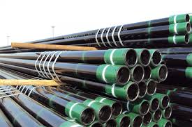
Oil casing is an important equipment for oil drilling. Oil casing is also called OCTG casing. It is mainly used to support the well wall and to ensure the progress of the drilling process and the normal operation of the entire oil well after completion. The supporting tools for oil casing include drill pipe, drill collar and tubing.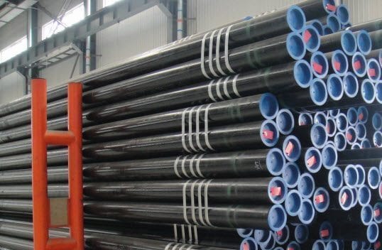
2. Casing quality inspection method
There are two commonly used methods for casing condition detection: the engineering logging method and the mechanical method. The engineering logging method uses calipers to detect changes in casing radial dimensions, and continuous flow and well temperature logging to detect the location of casing corrosion, holes, ruptures, misalignments, etc. The mechanical method uses impressions (including lead molds, film, wax molds, etc.) to verify the status and geometric shape of the casing and fish head, and then conducts qualitative and quantitative analysis to determine their specific shape and size.(1) Engineering logging
①Well diameter logging-----casing deformation detection
Well caliper logging is generally carried out in the well kill state. The most commonly used logging instrument at present is the 40-wall caliper, which can measure 20 coordinate points at an angle of 18° to each other.The recording paper for measuring casing deformation is divided into nine grids. If the casing is not damaged, it will be a relatively smooth straight line, with peaks appearing only at the coupling part; if the recording curve deviates from the reference line, there is deformation of the casing; if the recording line is a wavy line, it may be wear or corrosion of the inner wall; if If the curve exceeds the normal range, it indicates that the casing is perforated or cracked.
②Well temperature and continuous flow logging---casing oil and gas leakage detection
Well temperature and continuous flow logging are two different logging methods implemented on one well. If leakage is found in a well, first measure a well temperature baseline, then continuously inject liquid into the well and measure the continuous flow rate (injection volume) at different pressures. After injecting the liquid, measure the well temperature curve. From the comparison of the two well temperature curves, the well section with casing leakage can be analyzed and checked mechanically if necessary. In this way, the location of casing damage and the amount of oil and gas leakage can be accurately verified.a. Well temperature logging
Well temperature logging measures geothermal gradients and local temperature differences (microdifferential well temperatures). Copper, tungsten, molybdenum, or alloys are used as thermistors in the instrument circuit, which respond sensitively to temperature. As the temperature increases or decreases, the corresponding resistance changes. The temperature change is obtained indirectly by measuring the change in bridge potential difference. Downhole instruments send temperature signals to surface instruments to obtain geothermal gradient curves. If there is an abnormality in the ground temperature in a certain part, the well temperature curve will change significantly. By analyzing this change, you can obtain the temperature situation and its location underground.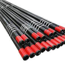
b. Continuous flow test
A continuous flow meter is a type of turbine flow meter. In this type of flowmeter, the measured fluid drives a turbine to rotate, and the turbine blades cut magnetic lines of force in the magnetic field, thereby converting them into electrical pulse signals and transmitting them to the ground. Commonly used for continuous measurement of water absorption in water injection wells. When used to detect lost circulation in wells with damaged casing, the injection volume of the lost well section and leaking point can be determined by continuously measuring the changes in the axial movement velocity of the fluid in the well.③Color ultrasonic television imaging logging
Color ultrasonic TV imaging logging technology can visually reflect the degree of casing damage on the TV screen. Combined with well diameter logging, the shape and size of casing damage can be quantitatively obtained.In the well-killing state, using the propagation characteristics of ultrasonic waves in media with different acoustic impedances and the reflection characteristics at the interface, and based on the arrival time of the received reflected wave and the first wave amplitude information of the first wave arrival, a rotating ultrasonic transducer is used to perform advanced With the assistance of advanced electronic technology and computer imaging technology, the inner diameter changes of the inner wall of the casing are obtained, and data such as three-dimensional views, longitudinal cross-sections, transverse cross-sections and inner diameter curves are displayed at the same time, so that the type and degree of damage to the casing can be visually judged.
④Impression and gyro azimuth logging
Impression and gyro azimuth logging (azimuth logging for short) is used to detect the azimuth direction of casing deformation. Based on the casing deformation orientation of multiple wells in the same area, the source of external forces for casing deformation can be basically determined, and the in-situ stress changes, external force directions, trends, etc. of casing deformation in the block can be calculated to provide guidance on how to improve the cementing quality of new drilling wells. Or change the cementing method to prevent casing damage to provide the necessary basis.The basic principle of azimuth logging is: use the lead mold, eccentric production distributor, working barrel, and tubing string to form a test string. Before the lead mold is put into the well, print a mark on a certain point on the working end of the lead mold and measure the mark and the eccentricity of the eccentric production distributor. After entering the well, the deformed part of the casing is printed, and then a gyroscope is run into the pipe string to measure the orientation of the eccentric hole. Pull out the printing pipe string, measure the position of the eccentric hole and the impression of the lead mold, and the angle between the impression and the mark at a certain point on the end face, and you can get the position of the sleeve change.
(2) Mechanical method
The mechanical method, that is, the impression method, uses a special pipe string (wire ropes can also be used with lead molds when conditions permit) connected with lead mold printing tools to print the fish top or casing damage degree (geometric shape) of the well drop. Then, the impressions made are described, analyzed, and judged, and finally the accurate geometric shape, size, and depth position of the fish top, casing damage point, etc. are proposed. This imprint conclusion and data will provide indispensable and effective basis for the formulation and compilation of workover measures and well workover construction design.Impression method detection is suitable for the verification of the geometry, size, depth, etc. of the fish top dropped by the well, the degree of casing damage such as deformation, staggering, and rupture of the casing, the verification of the depth position, and the temporary inspection during operations and workover construction. Well conditions where it is necessary to ascertain the technical condition of the casing and other conditions.
①Types of impressions
There are many types of impressions, generally classified according to manufacturing materials and basic structural forms.a.Manufacturing materials
It can be divided into the following types according to manufacturing materials- Lead impression--commonly known as lead mold;
- Glue impression--commonly known as glue mold;
- Wax impression--commonly known as wax mold;
- Clay impression--commonly known as clay mold.
b.Structure
According to the structure of the impression, it can be divided into the following types:flat bottom; conical; ring; concave; cylindrical.Currently, two types are widely used: lead mold and rubber mold. The most widely used lead mold is the flat-bottom lead mold with a water eye, and the widely used rubber mold is the packer-type rubber barrel-shaped lateral printing rubber mold.②Basic structure of lead mold and rubber mold
a. Lead mold
There are two types of lead molds with flat bottom and water holes: ordinary type and shielded type. The body of a typical lead mold is made of a welded skeleton of a 2/in internal flat oil pipe joint. There are generally no less than 4 steel bars for the skeleton, forming an angle of 90° to each other. For flat-bottomed lead molds with a shield, the gap between the shield and the oil pipe should be about 15mm.After the lead liquid is cast and formed, drill a 30mn~40mm water hole in the middle of the bottom end and level the end surface. Note that the thickness of the lead layer at the lower end should not be less than 20mm, but generally the thickness should not exceed 40mm. Flat-bottom lead molds are mostly used to assess the situation of fish falling downhole, as well as the degree of casing damage and depth. Tapered, annular, and concave lead molds are less commonly used.
b. Glue mold
Rubber molds are generally used to verify leakage conditions such as casing holes and ruptures, that is, printing on the side of the casing. Therefore, the rubber mold is also commonly known as the casing side printer. Its basic structural form is similar to that of the expansion packer, but it has fewer cords inside the rubber cylinder and a longer working surface. The rubber cylinder surface is semi-vulcanized and has a smooth and smooth surface. It is smooth and defect-free and can withstand 0.5~1.0MPa pressure.The Shore hardness of the surface of the glue slip should be maintained between 3040. The outer diameter of the maximum working surface should be 0.5~lmm smaller than the maximum outer diameter of the steel body to avoid scratching the rubber cartridge when entering the well. The length of the working surface depends on the length of the printing well section, and the length of the steel body center tube should match the total length of the rubber barrel.
③Impression printing (testing) construction method
Impression printing to detect the technical status of downhole technology is generally divided into three forms: printing of the top condition of downhole falling objects, printing of the minimum radial change of casing deformation and staggering, and side printing of casing rupture, holes, etc.
a.End printing
End printing, that is, printing of the condition of the underground fish top and the degree of casing damage. There are generally two methods of printing, namely the hard printing method of pipe strings and the soft printing method of ropes. Although the soft printing method has a short construction time and is fast, it is highly dangerous and can easily cause rope accumulation and jamming, so its use is strictly restricted in various oil fields. Hard printing can be performed in two operating modes: non-killing and well killing. The printing operation is safe and stable under the well killing state. Regardless of whether the well is killed or not, the lead mold shall not be directly pressed into the well through the self-sealing seal when entering the well. The following focuses on the operation method of non-stop well construction.Ⅰ.Pipe string structure
The pipe string structure from top to bottom is: oil pipe string (or drill pipe string), working barrel, check valve, and impression mold (flat-bottomed lead mold with water eye and shielded lead mold is commonly used for end printing).Ⅱ. Installation of wellhead control device for snubbing operation
The wellhead control device mainly consists of the following components (from top to bottom): safety slips, self-sealing well capping device and self-sealing core, flange nipple, semi-sealing well capping device, fully sealed well capping device, semi-sealing well capping device , any flange. The wellhead device should be installed flat, upright and firmly, and the tightening torque of each fastening bolt should generally not be less than 2800N.m.Ⅲ.Connecting downhole tools
Connect the working barrel and check valve to the lower end of the first well-entering oil pipe, tighten the torque to no less than 2400N·m, and apply sealing grease.Ⅳ.Impression into the well
Clean the lead mold, apply sealant to the threads, and record the shape of the end face of the lead mold. Lift the first oil pipe, insert the working barrel into the self-sealing core, then remove the self-sealing gland, press the safety slip handle so that the slip teeth bite the oil pipe, lift the oil pipe, and lift the self-sealing core at the same time as the oil pipe. , then connect the lead mold under the one-flow valve, and tighten the torque to no less than 2800N·m. Be careful not to scratch the lead mold. After tightening, lower the oil pipe, make the self-sealing core sit back in the self-sealing seat, tighten the gland, and then slowly lower it. After the first oil pipe is lowered into the well, the oil pipes are continuously lowered.
Ⅴ.Print
When the lead mold is lowered to the pre-printing depth of 1~2m, record the hanging weight of the pipe string, turn on the pump to circulate the working fluid, and rinse the fish head or casing damage point for 1~2 weeks. After it is normal, lower it for printing at a speed of 0.5~lm/s. Note that the hanging weight of the pipe column does not exceed 2~3kN, and it can only be printed once. Then measure the square footage of the last oil pipe and calculate the depth of penetration.
Ⅵ.Printing columns from
When starting the printing pipe string normally, when lifting to the last one, the lifting speed should be controlled within 0.5m/s. When the working simplex, one-flow valve, and lead mold enter the flange sub-section and are fully sealed, stop lifting. Press the safety slip handle, bite the oil pipe tightly, and then close the full seal. Note that the number of closing turns on both sides is the same. Open the vent valve to release the residual pressure in the flange nipple, and then the working barrel, one-flow valve, and lead mold can be lifted out.
Ⅶ.Remove the lead mold
Pull the last oil pipe with the lead mold out towards the oil pipe bridge, being careful not to scratch the lead mold. Remove the working cylinder, one-flow valve, and lead mold respectively, and clean the lead mold.Ⅷ.Imprint analysis
Determine the printing depth, calculate the deformation or fracture depth of the fish top, and trace the impressions on the end face of the lead mold.
b.Side printing
Side printing uses a pipe column to lower the side printing rubber mold to the designed depth, and then turns on the pump to hold down the pressure of 0.5~1MPa, so that the rubber mold expands under the hydraulic pressure and sticks tightly to the inner wall of the casing, eliminating holes, ruptures, etc. of the casing. The damage status is printed on the rubber mold. After the pipe string is depressurized, take out the printed pipe string, remove the rubber mold and clean it, connect the rubber mold to the surface pump, hold down the pressure to expand it to the working size downhole, and then the downhole casing can be clearly The damage status is intuitively reflected, and the geometric shape is accurate, and the damage size can be measured directly.This method is simple and easy to implement, and the data obtained are authentic and credible. Side printing can be performed without suppressing the well. The operation method of snubbing the pipe string is the same as that of lead mold snubbing.
Ⅰ. Pipe string structure
The pipe string structure consists of oil pipe string, working barrel, rubber mold, oil pipe nipple, and wire plug.
Ⅱ.Print
According to the lead mold non-pressure well printing method, lower the side printed rubber mold pipe string to the designed depth. After verifying that it is correct, pour clean water into the pipe string. When the pressure shows 0.5~1.0MPa, stabilize the pressure for 5 minutes to release the pressure in the pipe string. Take out the printing column and note that side printing can only be done once.Ⅲ.Imprint analysis
Remove the removed rubber mold, clean it, connect it to the surface pump, and use clean water to pressurize it to 0.5~1.0MPa to expand the rubber mold to the size of the underground working state. At this time, the rubber mold can remove the cracks and holes in the casing. When the degree of damage is clearly reflected, the impressions can be measured and traced, and can be photographed and archived to obtain the accurate size of the damage degree.
④Imprint analysis method
Imprint analysis is to measure, describe and compare the impressions of the impressions, and conduct qualitative and quantitative analysis and interpretation. The conclusions are used to guide the formulation of repair measures and the preparation of construction designs. At the same time, it also provides reliable basis for the research on the casing damage mechanism of casing damaged wells and the formulation of preventive measures.a.Drawing method
The drawing method is to clearly record and record the basic shape of the end face before the impression is put into the well, then the impression is printed into the well, and then the printed impression is measured, drawn and drawn. Compare the saved graphics with the impression depiction graphics to find out the basic change outline, and then analyze it.The center point of the impression coincides with the center vertical line of the casing, that is, the impression is basically centered when printing. The drawing method is to use the inner diameter of the casing as the diameter to draw a circle, then align the center point of the impression with the casing circle point to draw the pattern of the impression, draw a clear arc at the deformation of the impression and find the center of the arc, and at the same time The two points obtained by extending the arc and intersecting the casing circle are the basic points of casing deformation. The deformation arc of the impression (that is, the apex of the casing depression) is the starting point of the radial size of the casing after deformation.
If the impression is printed, the center of the impression deviates from the axis of the casing. If one side of the impression is close to the casing wall or touches the casing wall without scratches, and the other side is squeezed and has an obvious arc, which is a more typical single-dent deformation, then the minimum diameter of the impression is still not the deformation of the casing. Minimum diameter. If one side of the impression is close to the casing wall and is squeezed and has obvious scratches, and the other side is squeezed into an obvious arc by the top of the depression within the deformation of the casing, it basically shows the smaller or minimum diameter of the casing deformation.
b.Simulation method
The simulation method is based on the drawing method and uses corresponding casing or other similar pipe materials according to the shape and size of the impression to simulate the deformation, staggering, rupture, holes and other shapes of the downhole casing, which is consistent with the impression. The impressions are basically consistent, and then the damage to the casing can be visually observed. The biggest advantage of this simulation method is that the casing damage situation is intuitive, clear and accurate. The disadvantage is that it is more troublesome to make.At present, with the development and application of computer multimedia three-dimensional image software, computer-aided analysis and simulation of the technical status of downhole casing is no longer a problem. Based on the drawing method, the geometric shape and size of the impression mark are input into the computer to produce a three-dimensional image, which can intuitively and accurately display various damages of the downhole casing.


